

DVI compatibility for sticklers
Background
DVI is a digital video standard introduced in 1999 which is in the process of replacing VGA as the most common way to connect monitors to computers. DVI stands for digital visual interface. It was created to provide a standard way to transfer an image in digital form rather than in the analog form used by VGA. DVI is used almost exclusively in LCD panels but occasionally is also used in high-end CRT monitors. The DVI connector also optionally supports analog video signals as described below but DVI is used primarly in digital mode. If you're interested in technical information then you can download the DVI specification from here.
Why digital?
A video card maintains its screen image as a series of numbers stored in video RAM. Each number represents the color of one tiny spot on the screen called a pixel. An entire screen image is made up of a whole bunch of pixels. If your monitor is running at a resolution of 1024 by 768 then the screen image is made up of an array of pixels which is 1024 pixels wide and 768 pixels tall for a total of 786,432 pixels. There's more than one way to get that screen image made up of all those pixels displayed on your monitor. The standard way of getting the screen image to a CRT monitor (the ones which use a TV tube rather than a flat LCD panel) is the VGA system. VGA is an analog system which means that it converts the series of numbers which represent the screen image colors into analog voltages. Different voltages represent different colors. The video card sends those analog voltages through the VGA cable to the monitor. Then the electronics in the monitor displays colors which match the voltages which came through the cable. There's a number of problems with this system. First of all, the video card has to take the series of numbers in the screen image and convert them into a series of analog voltages. That conversion can degrade the image quality a little. Then the analog voltages have to be sent through the VGA cable where they can be degraded by electrical noise or by low-quality cables. The analog voltages which arrive at the monitor may be quite different from the original screen image numbers in the video card. With a good video card and high-quality VGA cable, the image quality can still be very good by the time it gets to the VGA monitor. But it gets more difficult to maintain good image quality as you increase the screen resolution or screen refresh rate.
If you use the VGA system to display images on an LCD monitor then it's even more complicated. The video card converts the image data into analog voltages and transmits it through the VGA cable as described above. But LCD monitors are digital devices rather than analog devices like CRT monitors. That means that LCDs display a color which matches a number rather than an analog voltage. So the analog voltage which arrives at the LCD monitor has to be converted back into a number so the LCD can display it. This is an extra conversion step which can degrade the image quality again. And if your video card is set to a resolution which matches the resolution of your LCD panel then you can potentially get very sharp images on the LCD. So if your video card is running at 1024 by 768 pixels and you're using an LCD panel which is also 1024 by 768 then you'd like to get each pixel in your video card screen image aligned with each pixel on your monitor. That's much sharper than what you can get on a CRT monitor. The problem is that if you use analog VGA to send the screen image to the LCD monitor, it can be difficult for the monitor to align each pixel in the screen image with the same pixel on the monitor. When it fails to align properly you can get a slightly jittery image where parts of the image move horizontally back and forth a little. It doesn't move very much but it can be quite annoying.
When it comes down to it, analog VGA is not a smart way to transmit the screen image to a digital monitor like an LCD panel. The video card already stores its screen image as a series of numbers which represent the screen pixels. The LCD monitor is a digital device which also displays a series of numbers. The analog VGA system converts the series of numbers in the video card into analog voltages, transmits them through the VGA cable, and then the LCD monitor converts the analog voltages back into numbers and tries to align the pixels on the LCD and display them. The obvious solution is to avoid ever converting to analog voltages in the first place and transmit the numbers from the video card to the LCD monitor in digital form. That avoids the conversion errors, analog degradation in the cable, and pixel alignment problems on the LCD monitor. If the digital transmission is working properly then your LCD ends up with an exact duplicate of the series of numbers which make up the screen image in the video card. There's no degradation of any kind getting from the video card to the LCD monitor. That's why they created DVI. It's a way of transmitting the screen image from your video card to your digital LCD monitor with no image degradation.
Many LCD monitors made before 2004 had visible degradation problems when displaying screen images transmitted using VGA. The color distortion wasn't usually that noticeable (unless you're very picky) but the pixel jittering could often be annoying. But most LCD monitors made since then use improved auto-synchronization circuitry which has largely eliminated pixel jittering. Unless you're really picky about your colors (a common situation while doing artwork) then you'll have a hard time distinguishing between the image quality when using analog VGA and digital DVI. Analog VGA on an LCD monitor is a lot better than it used to be. Nonetheless, if you want to get the best image quality possible then digital DVI is the way to go.
DVI-D, DVI-I, and (the extremely rare) DVI-A
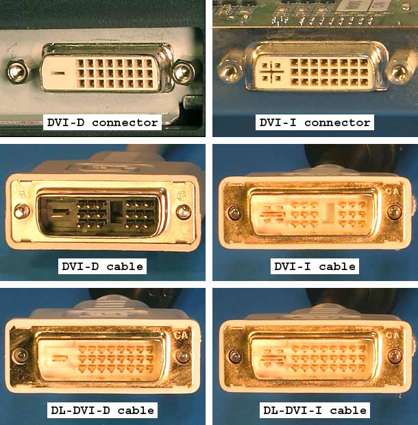
DVI was created to provide a high-speed digital interface for video signals. But the creators also wanted a flexible standard so DVI included support for an analog interface. The analog part of DVI is compatible with standard VGA monitors. There's actually three kinds of DVI: DVI-D which is digital only, DVI-A which is analog only, and DVI-I which includes both analog and digital (the "I" is for integrated analog and digital). The top row of the image below shows the kinds of DVI connectors which can be found on video cards and monitors. The bottom two rows show the matching cables.
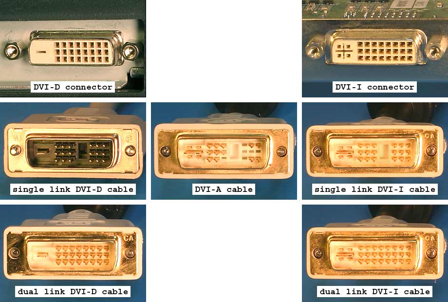
The two kinds of connectors are DVI-D and DVI-I. It's easy to tell them apart. DVI-I has a pair of slots which look like a plus sign with four sockets around it. DVI-D has a single slot which looks like a minus sign. Because of that physical difference, you can plug a DVI-D cable into a DVI-I connector but you can't plug a DVI-I cable into a DVI-D connector. A DVI-D cable is wired only for the digital video signal. DVI-D cables can't carry analog signals. A DVI-I cable is wired for both analog and digital video and can work in either mode. There are two different kinds of DVI-D and DVI-I cables: single link and dual link. The difference between them will be described later. DVI-A is very rarely used. A DVI-A cable is wired only for an analog video signal and can't carry digital signals. You'll note that there is no DVI-A connector shown in the image above. In the unlikely event that you come across a video card with a DVI-A output or a monitor with a DVI-A input, they'll use a DVI-I connector. A DVI-A cable fits into a DVI-I connector but won't fit into a DVI-D connector. The vast majority of analog monitors use VGA cables so DVI-A is very rarely used.
| DVI connector and cable compatibility | |||
|---|---|---|---|
| DVI-D cable | DVI-I cable | DVI-A cable | |
| DVI-D connector | Works in digital mode | Cable won't fit in connector | Cable won't fit in connector |
| DVI-I connector | Works in digital mode | Works in digital or analog mode | Works in analog mode |
| DVI-A connector (really a DVI-I connector but wired only for analog) | Fits in connector but doesn't work | Works in analog mode | Works in analog mode |
Most video cards use DVI-I connectors so they can support both analog and digital monitors using a single connector. Those video cards have separate circuitry to provide both analog and digital signals for the same video card output. There's usually limited space for video card output connectors so they need to fit both kinds of signals into the same connector. As of 2006, DVI-D video card connectors are far less common than DVI-I because they don't allow people to connect the still common analog VGA monitors.
DVI monitors which support only digital signals have a DVI-D connector. Virtually all monitors which support only analog signals have a VGA connector instead of DVI-A. And most monitors which support both digital and analog have both a DVI-D and a VGA connector. There are monitors which have DVI-I connectors to support both analog and digital, but as of 2006, they aren't common. When you're using a DVI-I monitor with a DVI-I video card then you can run in digital mode when using a DVI-D cable or you can run in analog mode when using a DVI-A cable (if you can find one). But if your video card, cable, and monitor are all DVI-I then they can use either analog or digital. You generally control whether to use analog or digital by using the monitor's on-screen display to select the appropriate input.
Making an analog connection
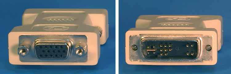
The most common way to connect a DVI-I video card to a VGA monitor is to use the adapter shown above. It's is a DVI to VGA adapter. You plug the adapter into the video card's DVI-I output and then plug the monitor's VGA cable into the VGA side of the adapter. The adapter simply takes the analog signals in the DVI-I connector and hooks them to a standard VGA connector. Since the analog signals in DVI are actually just normal VGA signals, all you need is a different kind of connector. You can also use the same adapter and a VGA cable to connect a VGA video card to a DVI-I monitor. The same adapter also works for a VGA video card and DVI-A monitor as well as a DVI-A video card and VGA monitor but it's unlikely that you'll ever run into those combinations. DVI-A video cards and monitors are extremely rare (if they exist at all).
You can use DVI-I and DVI-A cables and various kinds of adapters to make analog connections between video cards and monitors but it's rarely done. Most people only use analog connections when using existing analog monitors and almost all of them are VGA monitors which already have VGA cables. So even though DVI has support for analog signals in DVI-I and DVI-A cables, almost all analog video is sent using VGA cables. You probably don't need to own either a DVI-A or DVI-I cable.
Making a digital connection
When connecting a digital monitor to a video card, most people use a DVI-D cable. Most monitors have only DVI-D connectors. You can't plug a DVI-I cable into a DVI-D monitor because the cable won't fit in the connector. Most video cards have DVI-I connectors because they support both analog and digital video. But some video cards have DVI-D connectors which means you can't use a DVI-I cable. I suspect that most DVI-I cables are purchased by mistake. People are hooking a DVI monitor to the DVI connector on the video card and assume that a DVI-I cable will work because it supports both analog and digital. It sounds like a universal cable. Then they discover that they can't use a DVI-I cable because either the monitor or video card has a DVI-D connector. The easiest way to deal with the issue is to use only DVI-D cables and avoid DVI-I cables. That's the standard solution: use VGA cables for connecting VGA monitors and use DVI-D cables for connecting digital monitors.
Single link and dual link
DVI transfers its digital data over a set of wires known as a link. The link has a maximum allowed data rate to make sure that the data gets from the video card to the monitor without being corrupted. The maximum DVI data rate for a link is 165 MHz. This data rate is usually called the pixel clock. The higher the screen resolution and screen refresh rate the more data which has to be transferred. For example, a monitor running at 640 X 480 with a 60 Hz refresh rate and standard timing has a pixel clock of 25 MHz. 1600 X 1200 at 60 Hz requires a pixel clock of 162 MHz which is almost the maximum which can be handled by one DVI link. Some high-resolution monitors need screen modes which require more than 165 MHz so DVI supports an optional second link to double the data rate. The table below shows some common screen modes and their pixel clocks. Timings vary a bit so the numbers for a given screen mode on a given piece of hardware may be somewhat different from these.
| Screen resolution | Refresh rate | Total data rate | Link pixel clock |
|---|---|---|---|
| 640 X 480 | 60 Hz | 25 MHz | single link @ 25 MHz |
| 1024 X 768 | 60 Hz | 65 MHz | single link @ 65 MHz |
| 1024 X 768 | 75 Hz | 79 MHz | single link @ 79 MHz |
| 1280 X 1024 | 60 Hz | 108 MHz | single link @ 108 MHz |
| 1280 X 1024 | 75 Hz | 135 MHz | single link @ 135 MHz |
| 1680 X 1050 | 60 Hz | 146 MHz | single link @ 146 MHz |
| 1280 X 1024 | 85 Hz | 158 MHz | single link @ 158 MHz |
| 1600 X 1200 | 60 Hz | 162 MHz | single link @ 162 MHz |
| 1920 X 1080 | 60 Hz | 173 MHz | dual link @ 86.5 MHz |
| 1920 X 1200 | 60 Hz | 193 MHz | dual link @ 96.5 MHz |
| 1600 X 1200 | 75 Hz | 203 MHz | dual link @ 101.5 MHz |
| 2048 X 1536 | 60 Hz | 267 MHz | dual link @ 133.5 MHz |
All digital DVI implementations are required to implement one link. They may also optionally implement a second link to support data rates higher than 165 MHz. Any screen mode which fits in 165 MHz uses only a single link even if the video card, video cable, and monitor all support dual links. The second link is used only if the screen mode requires more than 165 MHz. As of 2006, the majority of video cards are single link DVI implementations. Dual link cards are less common. As time passes, a larger fraction of video cards will ship with dual links because high resolution monitors are becoming more common.
There is no requirement that a DVI implementation be able to go as fast as 165 MHz. DVI implementations only need to have a high enough pixel clock to implement the supported screen modes. Support for the 165 MHz pixel clock has at times been spotty in consumer-oriented video cards. The quality of the digital signal at 165 MHz varies between different video card models. It can even vary among different versions of the same model. The DVI implementations which came out when DVI was new were the most problematic. Some of NVIDIA's older DVI implementations do not work well at 165 MHz. Many cards from the GeForce 5 series and some from the GeForce 6 series can corrupt the screen image if pushed beyond about 130 MHz. A video card uses a DVI transmitter to send the digital data from the video card to the monitor. Some DVI transmitters are built into into the GPU (integrated transmitters) to save costs and other DVI transmitters are in separate silicon chips (external transmitters) which makes them a bit more expensive. The integrated transmitters in the GeForce 5 and 6 series give much worse performance than most external transmitters. Some GeForce 5 and 6 cards use external transmitters to support higher pixel clocks but the cheaper cards almost always use the integrated transmitter rather than an external one. Many older NVIDIA video cards with two separate DVI outputs use an integrated transmitter for one output and an external transmitter for the other output. As a result, one of the outputs is often much better than the other. ATI video cards also can use either integrated or external transmitters. Unlike NVIDIA, ATI's original DVI integrated transmitters almost always run properly at the full 165 MHz so you don't run into the problems with older ATI cards which you see in older NVIDIA cards. You can read about DVI transmitter quality in older video cards here and here. Most of the older problematic DVI implementations are good enough to support 1280 X 1024 at 60 Hz with a 6 foot (2 meter) cable without problems.
Dual link DVI cables are usually called "DL-DVI" for short. The image above shows the various single and dual link DVI cables. The single link cables are missing the six pins used by the second link. There's no such thing as a single link video card or monitor connector. Connectors always have the full three rows of eight holes whether they're single link or dual link hardware. So you can't tell whether a video card or monitor is single link or dual link by looking at the connector. You have to check the video card or monitor specifications to know how many links are supported. Both single link and dual link cables fit into both single and dual link video cards and monitors. So single link cables fit into dual link video cards and monitors and dual link cables fit into single link video cards and monitors.
The compatibility rule between single and dual link DVI hardware is simple: if the video card, DVI cable, and monitor all support dual link then the setup as a whole supports both single link and dual link screen modes. If one or more of the video card, cable, and monitor support only single link then the setup supports only single link screen modes.
DVI-D cables fit into both DVI-D and DVI-I connectors whereas DVI-I cables do not fit into DVI-D connectors. And a dual link cable will function just fine in a single link setup as described above. As a result, the most useful kind of digital DVI cable is a dual link DVI-D cable. People rarely use the analog lines in a DVI-I cable so there's not much point in getting one of those. Dual link DVI-D cables are the "universal" digital cable.
Cable quality
An interface like VGA or DVI-A transmits the video signal in analog form. The analog video signal can degrade while traveling through cheap cables. Just about any 6 foot (2 meters) long monitor cable can display a 1024 X 768 image at 75 hertz with minimal degradation. But going much above that requires a high-quality cable to keep the image from deteriorating. Longer analog cables make the degradation worse so you have to be especially careful when using long cables. There's a real difference between crummy analog video cables and good ones. A bad analog cable makes the image on the monitor look smeared. It can also causing ringing in the signal following sudden color changes. The ringing looks like small horizontal wobbles in the color which go from left to right. Low-quality analog video cables tend to be thin and use twisted pair wires for the image signals. High-quality cables are thicker and use thin coaxial cables for the image signals. The specifications for good analog cables usually mention "coax" or "coaxial" whereas the cheaper cables made with twisted pairs usually don't mention the type of cable. High-quality cables also have ferrites at the ends to reduce electrical and radio noise. The ferrites are the cylindrical objects near both ends of the cable.
With analog video, the image quality can be anywhere in a range from excellent to terrible with all points in between. The image quality drops off smoothly based on the quality and length of the cable. But digital video is different. It only has two kinds of image quality: perfect, and seriously screwed up. Occasionally you can get digital video problems which are only mildly annoying but usually it's at one extreme or the other. It doesn't have the smooth drop off in quality that you get with analog signals. So all you really need to use is a properly constructed digital cable and there's no point in spending any extra money. Competently built digital cables should deliver a perfect image which is identical to the image in the video card. It still is possible to build cheap DVI cables which can screw up the image, especially if you're running at high screen resolutions and refresh rates or are using a long cable. But a run-of-the-mill 6 foot (2 meters) DVI cable should deliver the exact same image as a substantially more expensive, premium cable. With analog video cables it pays to be careful about quality. With digital cables you just have to avoid crappy ones.
Reduced blanking
To understand blanking time it helps to understand the basics of how CRTs display images. CRTs work by by shooting a beam of electrons at phospors on the front surface of the CRT tube. The phospors glow for a little while after being hit by the electrons. CRTs use this glow to draw an image on the front of the tube. A CRT draws a screen image starting at the upper left corner. It moves the electron beam from left to right across the screen to draw the top row of the image. It turns the electron beam on and off as it moves from left to right to draw the row. When it has reached the right-hand side, it moves the beam back to the left and down by one row. That move is called a horizontal retrace. Then it draws the next row from left to right. It repeats this process to draw the rows successively from top to bottom on the screen. When the electron beam reaches the bottom of the screen it does a vertical retrace to move it back to the top so it can start the next screen image. During these horizontal and vertical retraces the electron beam is not actually drawing the screen image. It's just moving around to get it in position for the next draw. The CRT also has to spend time dealing with the empty border outside of the screen image. As a result, a CRT spends a substantial portion of its time doing retraces and other things which are not part of drawing the visible screen image. The timing can vary quite a bit among different screen modes, but for standard CRT timing about 70% of the time is spent drawing the screen image and the other 30% is invisible overhead. This overhead is often called "blanking time" because the signal is blank (shut off) while not drawing the visible screen image.
Blanking time is needed only by CRT monitors. LCD monitors don't have electron beams. LCDs just store the incoming image data directly into memory which is displayed on the screen. There's no need for retrace times or most of the other overhead required by CRTs. But DVI was designed to support both CRTs and LCDs so it sends out a digital signal which closely resembles the old CRT's timing including the blanking time overhead. LCDs don't need that extra overhead but it's in the DVI video signal anyway. Recall from the earlier single link and dual link section that a single DVI link has a maximum pixel clock of 165 MHz. For an LCD, the blanking time's portion of that 165 MHz is wasted due to using CRT timing. When connected to an LCD it would be awfully nice to be able to get rid of that overhead because you could display the same screen resolution and refresh rate with a lower pixel clock. A lower pixel clock means the data is less likely to be corrupted going through the cable. It's also easier on the DVI transmitter which can be useful if you have one of the NVIDIA cards with a slow transmitter. You could also get away with using a longer cable before the screen gets corrupted. With the blanking time overhead removed, you can use a higher screen resolution and refresh rate before having to resort to using a double link setup. Lots of things get better for DVI if you can get rid of the CRT overhead when using an LCD. Fortunately, there's a fairly well standardized reduced blanking video format which reduces the overhead to about 5%.
| Screen resolution @ 60 Hz | Standard blanking DVI pixel clock | Reduced blanking DVI pixel clock |
|---|---|---|
| 640 X 480 | 25 MHz - single link @ 25 MHz | 24 MHz - single link @ 24 MHz |
| 800 X 600 | 40 MHz - single link @ 40 MHz | 36 MHz - single link @ 36 MHz |
| 1024 X 768 | 65 MHz - single link @ 65 MHz | 56 MHz - single link @ 56 MHz |
| 1280 X 1024 | 108 MHz - single link @ 108 MHz | 91 MHz - single link @ 91 MHz |
| 1680 X 1050 | 146 MHz - single link @ 146 MHz | 119 MHz - single link @ 119 MHz |
| 1600 X 1200 | 162 MHz - single link @ 162 MHz | 130 MHz - single link @ 130 MHz |
| 1920 X 1080 | 173 MHz - dual link @ 86.5 MHz | 139 MHz - single link @ 139 MHz |
| 1920 X 1200 | 193 MHz - dual link @ 96.5 MHz | 154 MHz - single link @ 154 MHz |
| 2048 X 1536 | 267 MHz - dual link @ 133.5 MHz | 209 MHz - dual link @ 104.5 MHz |
The table above shows the DVI pixel clocks of some common screen modes using both standard blanking and reduced blanking. Timings vary a bit so the numbers for a given screen mode on a given piece of hardware may be somewhat different from these. Note that both the 1920 X 1080 and 1920 X 1200 screen modes require dual link for standard blanking but will fit into a single link setup with reduced blanking. 1600 X 1200 and 1680 X 1050 with standard blanking can cause problems for weak DVI transmitters like on some older NVIDIA cards, but with reduced blanking they run at pixel clocks which rarely cause problems. Reduced blanking is really helpful in those kinds of cases.
Most LCD monitors made before 2004 don't support reduced blanking. Most LCDs made since then support reduced blanking in the helpful cases mentioned above. The monitor manual often includes a list of the supported display modes. Any reduced blanking modes will normally mention that they have reduce blanking or they'll mention the term CVT-RB (coordinated video timing- reduced blanking). If a video card enables a reduced blanking screen mode which is not supported by the monitor then the screen will go blank and display "no signal" or something similar. Some LCD monitors will go ahead and display non-supported screen modes but will end up with a distorted or clipped image. The hardware in all DVI video cards is capable of generating reduced blanking screen modes but it must be supported in the display driver. Any recent display drivers should support reduced blanking to support running 1920 X 1080 and 1920 X 1200 monitors with single link video cards. Some really old drivers may not support reduced blanking in which case you should just install the latest drivers.
Display drivers automatically choose when to use a reduced blanking screen mode. The normal Windows methods of setting a screen resolution and refresh rate don't allow you to manually select reduced blanking. If you have a single link setup and are displaying a mode like 1920 X 1200 at 60 Hz then the video card must have selected reduced blanking. But in other cases it may not be obvious. Some drivers seem to be aware of the limitations of their DVI transmitters (those that don't work well close to 165 MHz) and automatically select reduced blanking screen modes to reduce the DVI pixel clock to an acceptable value. I don't know of any standard way to tell if your DVI setup is using reduced blanking. The on screen displays of many monitors can display the DVI pixel clock. It's usually in the information screen and is most commonly called "pixel clock" or just "clock". If your monitor displays the pixel clock then you can compare with the table above to determine whether it's using reduced blanking. Keep in mind that the numbers may be slightly different than the table values. But if you need to try out reduced blanking to solve a problem, both ATI and NVIDIA have provided ways to do it.

The screenshots above show ATI's DVI controls for the older control panel version of their display drivers and for the newer Catalyst Control Center version. The "Reduce DVI frequency on high-resolution displays" and "Alternate DVI operational mode" checkboxes affect DVI. Unfortunately, ATI never clearly defines what either of them actually do. The "Reduce DVI frequency" checkbox sounds like the one which enables reduced blanking. I'm not really sure what the "Alternate mode" checkbox does. I've seen cases where both checkboxes have made DVI artifacts get better, get worse, or have no affect at all. Some people get better results with them unchecked and others do better with them checked. The best thing to do is try all four combinations of checking and unchecking those two boxes and see which one works best.
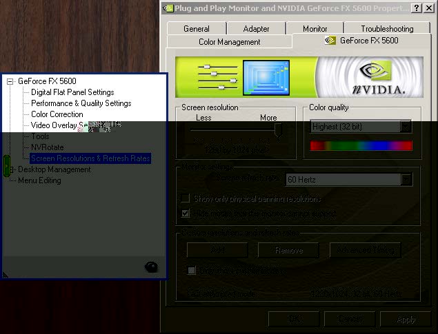
The screenshots above show the parts of NVIDIA's older control panel user interface which deal with reduced blanking. If you're using the old control panel then select the "Screen Resolutions & Refresh Rates" page. Then click the "Advanced Timing" button. If you have an older NVIDIA card then the advanced timing button may not appear if the DVI connection is using a DVI transmitter integrated into the GPU. If the card has two DVI outputs then you should connect your monitor to the other and try again because one may use an external transmitter while the other uses an integrated transmitter. If you don't see the advanced timing button then update to the latest display drivers in case they have added support for it. If you can't get the advanced timing button at all then you should try to use the newer NVIDIA user interface shown below. Those newer drivers are more likely to allow you to fiddle with the advanced timings. If you have the "Advanced timing" button then go to the "Timing standard:" list and select "Coordinated Video Timing - Reduced Blanking (CVT-RB)". Don't touch any of the other controls. They're not necessary to set up reduced blanking and can really screw things up if you don't know what you're doing. The "Pixel clock" field in the lower right-hand corner is the DVI pixel clock (the one which goes up to 165 MHz). That value should go down when you select reduced blanking. Press the apply button and cross your fingers. If your LCD doesn't like the new settings then do nothing and it will revert to your old screen mode after fifteen seconds.
The screenshots above show the new NVIDIA user interface. It's pretty but it also requires more steps to get the job done. The first thing you have to do is make sure that you're in advanced mode. You can't control reduced blanking while in standard mode. Once you're in advanced mode, click the big pretty picture named "Display".
That brings up the items which apply to your display. Click the "Manage custom timings" link.
Now you're looking at the "Manage custom timings" window. Click the "Create" button.
Now you're looking at the short version of the "Custom timings" window. Click the "Advanced >>" button in the lower right-hand portion of the window.
You are finally looking at the window which controls reduced blanking. Go to the "Timing standard:" list and select "CVT reduced blank". The new pixel clock is displayed in the "Pixel clock:" field. Then click the "Test" button to try out the new reduced-blanking screen mode. If the new mode works properly then click "OK".

Now you'll have the new custom timing shown in the list. Put a check in the "Allow modes not exposed by the display" check box. That will make sure that your new mode shows up in the list of display modes presented by Windows.
Troubleshooting
DVI is designed to be plug and play. You're supposed to plug the video card and monitor together and they automatically configure themselves for optimal performance. That's how it usually works. But if you're having problems then read through this page.
Home| Contact | Products | Support |Infomation |||
![]()